Kubernetes Architecture
A Kubernetes cluster consists of two main parts: the Control Plane (master node) and the Worker Nodes. Together, they manage and run containerized applications.
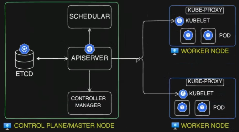
A Kubernetes cluster consists of two main parts: the Control Plane (Master Node) and the Worker Nodes. Together, they manage and run containerized applications.
1. Control Plane Components (Master Node)
Section titled “1. Control Plane Components (Master Node)”The Control Plane makes global decisions about the cluster, such as scheduling, and detects/responds to cluster events.
kube-apiserver: The front door for the Kubernetes control plane. It exposes the Kubernetes API.- It is the only component that directly communicates with the
etcddata store. - All components (internal and external) communicate through the API server via a “watch” loop or direct requests.
- Responsible for authentication, authorization, and validation of requests.
- It is the only component that directly communicates with the
etcd: A consistent and highly available key-value data store.- Stores the absolute current and desired state of the cluster, configurations, and secrets.
- If you lose
etcddata, you lose the cluster state.
kube-scheduler: The dispatcher. Monitors newly created Pods that have no assigned node.- Selects a suitable node for the Pod to run on based on resource requirements (CPU/Memory), constraints, affinity/anti-affinity rules, and data locality.
kube-controller-manager: A daemon that embeds the core control loops (controllers) of Kubernetes.- It continuously compares the actual state of the cluster to the desired state and reconciles them.
- Key controllers include:
- Node Controller: Notices and responds when nodes go down.
- Job Controller: Watches for Job objects representing one-off tasks, creating Pods to run them to completion.
- ReplicaSet Controller: Maintains the exact desired number of identical Pods for a deployment, replacing them if they crash.
- cloud-controller-manager (Optional): Links your cluster into your cloud provider’s API (AWS, Azure, GCP). Manages cloud-specific resources like external load balancers and block storage volumes.
2. Worker Node Components
Section titled “2. Worker Node Components”Worker nodes run the application containers and are managed by the control plane.
- kubelet: The node’s primary agent.
- Listens to the
kube-apiserverand ensures that containers are running inside their assigned Pods. - Continuously reports the health and status of the node and its Pods back to the API server.
- Listens to the
- Container Runtime: The software responsible for actually pulling images and executing containers via the Linux kernel.
- Modern Kubernetes strictly uses runtimes that comply with the CRI (Container Runtime Interface), such as
containerdorCRI-O. Docker (dockershim) is bypassed entirely.
- Modern Kubernetes strictly uses runtimes that comply with the CRI (Container Runtime Interface), such as
- kube-proxy: The node’s internal routing agent.
- It maintains network rules (usually via
iptables) on the host OS. - It translates permanent, virtual Service IPs into the actual, ephemeral IP addresses of living Pods so internal traffic routes correctly.
- It maintains network rules (usually via
- CNI (Container Network Interface) Plugin: (e.g., Calico, Flannel).
- Provisions the network namespaces for Pods, assigns them fully routable IP addresses, and establishes the virtual ethernet cables for inter-node communication.
3. Scenario: Admin Requesting to Create a Pod
Section titled “3. Scenario: Admin Requesting to Create a Pod”The exact step-by-step workflow when applying a YAML manifest:
- Request Submission: The user runs
kubectl apply -f pod.yaml, sending a declarative request to thekube-apiserver. - Authentication & Validation: The
kube-apiserverauthenticates the user, checks authorization, and validates the YAML structure. - etcd storage: The
kube-apiserverwrites this “desired state” toetcdand returns an “OK” to the user. - Pod Scheduling: The
kube-scheduler(watching the API) notices the new Pod object with no assigned node. It calculates the best fit and sends a binding request back to thekube-apiserver. - etcd Update (Binding): The
kube-apiserverupdates the Pod entry inetcdwith the assigned worker node’s name. - kubelet Notification: The
kubeleton the assigned node (watching the API) notices a Pod has been scheduled to it. - Network Setup: The CNI plugin provisions the Pod’s network namespace (
pausecontainer), assigns it a routable IP address, and attaches the virtual ethernet interface. - Container Creation: The
kubeletsends a gRPC request to the Container Runtime (containerd), which pulls the image and instructsruncto start the application process inside the shared namespace. - Service Routing Update: If the new Pod belongs to a Service,
kube-proxy(on all nodes) updates its localiptablesso cluster traffic can find the new Pod’s IP. - Status Update: The
kubeletmonitors the running container and reports its “Running” status back to thekube-apiserver. - Final State: The
kube-apiserverupdates the final state inetcd.
Would you like to continue building out these notes by adding the pure logic behind how storage volumes (PersistentVolumes and PersistentVolumeClaims) attach to these Pods?